[Note: I'll be adding photos to this as soon as I get them taken, developed, and scanned]
Even within the first week of receiving my CCD camera, it became obvious that hauling telescope, camera, tripods, computer, monitor, keyboard, mouse, cables, etc. outdoors, setting it all up, aligning the scope, and finally doing some imaging was not a good solution. It was taking nearly as much time to set everything up and tear it all down as was being spent on actually using the system. Something had to be done. The decision was made to construct a roll-off roof building in the backyard. I will present details of the design and construction in this article.
The telescope I use is a 10" Meade LX200 with SuperWedge. The camera is a Meade Pictor-416XT.
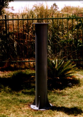
We decided to design the pier first, since the telescope is really the most important item in this scenario. The pier needed to be approximately 3 feet tall to give us a comfortable observing height. There are a lot of trees and other obstructions in our area, so we decided to add an additional two feet of height to improve visibility, for a total of 5 feet in height.
After talking to a few others who had constructed their own piers, plus reading an article or two in Sky & Telescope, we decided that 8 inches in diameter would be appropriate. To this 5' by 8" steel tube, we decided to mount a solid 3/4" thick 16" diameter steel plate to the bottom to serve as a base and a 1/2" thick 12" OD, 6" id steel plate "washer"/"doughnut" to the top to serve as a mount for the scope. The 6" id hole was necessary to allow ample room to pour sand into the tube for vibration dampening purposes. In addition, four 6" tall triangular fins would be installed on the bottom plate to tube surface for additional stability.
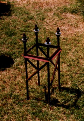
A friend who operates a large overhead sign company was able to make the pier for us out of materials that he had readily available at his business. The total weight of the assembly was approximately 210 pounds. He also welded together a "j-bolt cage" to be mounted into our concrete base. The j-bolt cage provides a very sturdy mount for bolting the pier down, and is the same type used in mounting large billboard-size signs.
Detail of Pier and j-bolt cage:
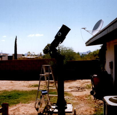
We poured an (approximately) 3 foot by 3 foot square by 2 foot deep concrete pad and mounted the j-bolt cage in it. This required approximately twenty 80-pound bags of concrete. Once the concrete was suitably cured, we poured sand into the tube to dampen vibrations. This required approximately 2.5 60lb bags of sand.
Detail of pier mounted to concrete pad w/ Telescope
With the pier constructed and ready for use, it became necessary to devise a way to securely mount the Meade SuperWedge. The SuperWedge requires one large 1/2" bolt in the center, 3 smaller bolts to serve as additional supports, and a slot for the azimuth pin to ride in. Since the "washer" on top of the wedge was not readily suitable for this purpose, we purchased a 14" diameter 1" thick steel plate.
We placed this plate atop the "washer" on the pier and drilled and tapped four bolts going from the pier up into the plate. Fiber washers were placed between the pier "washer" and the plate to correct for some imperfections in the pier's surface. Once bolted together, we had a very sturdy, flat, and heavy mounting surface to work with.
We removed the plate and drilled one 1/2" diameter hole in the center to hold the bolt that would go through the center of the wedge. This bolt was placed "pointing up" and welded in place using a wire-feed welder. We then returned the plate to the top of the pier and placed the wedge on top. The wedge didn't sit properly because we still hadn't drilled the slot to hold the azimuth adjustment pin. We were able to make an approximate daytime alignment on Polaris using a compass, mark the position for the azimuth adjustment pin, remove the wedge, and drill a spot for it. After this was done, the wedge sat flat on the surface and the azimuth adjustment was function.
Next, we mounted the telescope and waited for darkness to perform a rough alignment and verify that everything was set up properly. Once we had everything in the right place, we marked the positions for the 3 additional wedge support bolts, disassembled everything, and drilled and tapped the three holes.
As a final step, we used an electric sander with medium and then fine sand paper to sand away an abrasions and/or flaring left on the surface from the drilled and tapped holes. After this was done, everything was reassembled, aligned, and bolted into place.
We wanted an approximate 8' by 8' building to give us ample room around the scope. However, due to restricted space in our yard, we had to reduce the building width to 6'. The actual observatory area was thus 8' by 6' and the telescope would be centered in that area. We also wanted some room for a desk and storage space, so we added an additional 3 feet of space to the 8 foot dimension, for a total building size of 6' by 11'.
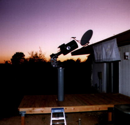
Since we had added 2' of height to the scope to correct for viewing obstructions, it was necessary to build the floor elevated 2 feet off the ground. We did this by mounting 6 4x4 posts to concrete pads at the corners and midway points of the building. These 4x4 posts were 18" tall. Atop the 4x4 posts, we constructed a framework of 2x6 lumber, thus leading to a total height of 24". 2x6 boards were placed every 16 to give adequate support. An air-powered framing nailer made the construction of the floor very easy. 3/4" plywood was then mounted and attached using a smaller brad nailer and screw gun. At this point, we had a very sturdy deck, 2' off the ground.
Detail of floor, pier, and scope:
At this point, we needed to decide the dimensions for the walls. The building would be constructed as a main 6' by 8' section for the scope with a roll-off roof, and the additional 3' section with a fixed roof tacked onto the northern end for the computer and storage. We wanted to be able to see Polaris, while still having a good southern view. In Tucson, Polaris is at a fairly low altitude and this limited the height of the northern wall to 6'6". Setting the telescope as low as it could go to clear the roof, we ran a string to determine the minimum height of the southern wall at 5'6". We arbitrarily decided to make the back (computer/storage) wall 4' tall.
Once these dimensions were calculated, we framed the walls using 2x4 lumber, one horizontal runner on the bottom and two on top, and a vertical every 16" inches. Framing was easily accomplished using a large skill saw to cut the 2x4's and the framing nailer to nail it all together. We cut and mounted 4x8 sheets of hardboard siding to the outside so as to match our house.
For an entryway door, we purchased a solid core 3' wide by 6'8" tall wood door. This door was significantly too tall for our building, so we cut the lower 12" off the door with a skillsaw. It was a tight fit, but it did work.
The separate hard roof for the 3' computer/storage area was easily constructed out of 1/2" plywood. It should be noted, that adding this short roof for the back section considerably stiffened up the rest of the building which was quite sloppy beforehand (after all, most people don't build roofless buildings!)
We now needed to figure out the 6' by 8' roll-off roof. We had originally planned on building a hard roof and roll it off by hand, but this seemed a bit tedious. Instead, we looked around and found a place that sold roll-up storage room doors. These doors are intended to be placed vertically and roll into a large coil at the top. They are commonly used in self-storage businesses. They are very much like a garage door, but have a large spring-loaded roll that the door retracts into. We settled on a 8' by 8' door since it was the closest standard size to our 8' by 6' roof. The door was mounted so as to retract off the western side of the building.
It should be noted that these doors are not really intended to be used as a roof and as such we had to make considerable modifications to the mounting brackets. We attached some 6" by 12" place steel to the mounting brackets so that we could extend them 4 inches off the sides of the building (the brackets to hold the roller require 4"-5" of additional clearance beyond the size of the opening). Careful measuring allowed us to get the brackets mounted at the correct height the first time! Then came the task of lifting the 200lb door/roller assembly into place. This was quite a task for two people and a third person would have made it much easier. Nevertheless, after some struggling with it, we managed to do it.
After the roller was mounted, we unrolled the door across the roof, and marked the positions for the two side rails/guides that hold the door in place. We then drilled and bolted on the side rails.
Once everything was done, we spring tensioned the roller on the door so that it would retract easily. Unfortunately, in it's normal installation, the door would be mounted vertically and gravity would assist in pulling it down. However, in a horizontal installation that isn't the case, and it's a chore even for two people to extend it against the spring tension. Something needed to be done.
We contrived a system of pulleys, cable, and a winch to assist in operating the door. Two pulleys would be mounted to the edge of the door (one on the northern side, one on the southern). To these pulleys, a cable was mounted which would be used to pull the door across the roof. A third pulley was used to angle the cable down the side of the building, to where the winch was mounted. Hopefully a picture will explain this a bit better than words.
![]() Return to Scott's Setup
Return to Scott's Setup